Overview
Welcome to the documentation for the Lidar Toolkit Plugin for Unreal Engine. This plugin allows you to scan 3D environments, capture point clouds, and export data in .xyz format for further analysis. While it is primarily designed to work with the Quixel Megascans vegetation library, it has been built to robustly integrate with most of Unreal’s collision and material systems.
If you use LiDAR toolkit for help with a publication, please cite: Stone, Gunner, and Alireza Tavakkoli. "LiDAR Toolkit: Scalable and Efficient LiDAR Simulation for Computational Research in Unreal Engine 5." Practice and Experience in Advanced Research Computing 2025: The Power of Collaboration. 2025. 1-4.
Getting Started
Once the plugin is installed, you will have access to a new GameMode called LaserScannerGameMode.
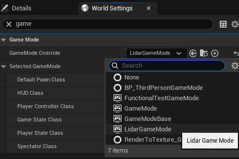
To use the plugin, you need to change the GameMode in the World Settings panel:
Open World Settings (if it's not visible, enable it via Window → World Settings in the Unreal Editor).
In the GameMode Override dropdown, select LaserScannerGameMode.
For a fast and easy demo of the plugins capabilities:
- Open up the demo level (verify that the gamemode is set to LaserScannerGameMode), and play the level in the editor.
- Navigate your free-cam to the base of a tree (hold left-click while panning the mouse to move camera viewing angle; hold left-click while using WASD to move).
- Press <Place Scanners> button on the HUD.
- Press <Start Scanning> button on the HUD.
- Watch as the lasers begin scanning their environment (and the trees!). If your don't want your game running at a low framerate; set <PointsPerFrame> in the HUD to a low value (like 1) and <Place Scanners> again to respawn the scanners with your new <PointsPerFrame> setting.
- After scanning is finished, click <Export PointCloud> and select an appropriate directory for the .xyz to be created.
Scripting Customization & Flexibility
Using the custom LaserScannerGameMode enables the player free-cam and scanner HUD, which serve as user-friendly interfaces to configure the LaserScanner class. They modify constructor properties and function arguments, allowing you to set up custom scans without writing any code.
If you need additional customization or cannot afford to change the GameMode in your project, you can bypass the built-in system and directly use the LaserScanner class in your own scripts. Simply call its functions programmatically to integrate it into your existing setup.
Out of the box, the plugin provides a complete solution for most scanning use cases—no coding required! However, if you need deeper control, the option to extend and modify the functionality is always available
Understanding the HUD
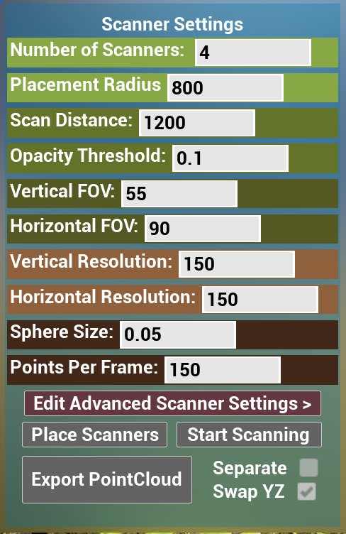
If you want to take full advantage of the out-of-the-box functionality of this plugin, understanding the HUD and its customizable scanner settings is essential. The HUD provides an intuitive way to configure and control scanning parameters without needing to modify code.
Number of Scanners
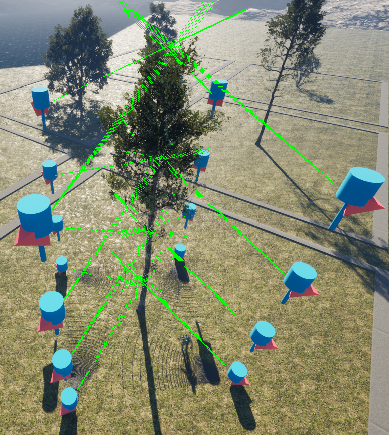
This determines how many scanners are spawned when you press the Place Scanners button. By default, scanners are positioned equidistantly in a ring around the player's current location.
Tip: For your first scan, stand near the base of your object of interest. This allows you to see how the scanners are positioned relative to it.
Placement Radius
This value determines how far away the placed scanners are from the player when placed.
Scanning Distance
This value sets the maximum range of a laser before it counts as a miss if it fails to hit something. In Unreal terms, this sets the Trace-End of the linetrace relative to the scanner's position.
Horizontal & Vertical FOV
These values determine the scanner’s Field of View (FOV) in degrees:
The Horizontal FOV defines the left-right sweep. If set to 90°, the scanner covers 45° to the left and 45° to the right from the scanner's forward direction.
The Vertical FOV works the same way but in the up-down direction.
Horizontal and Vertical Resolution
These determine how many rows and columns of scanned points will be captured. Each scan is divided equally across the FOV.
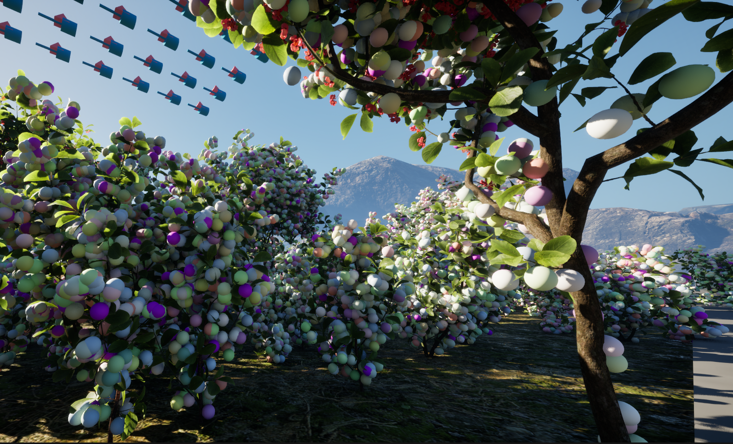
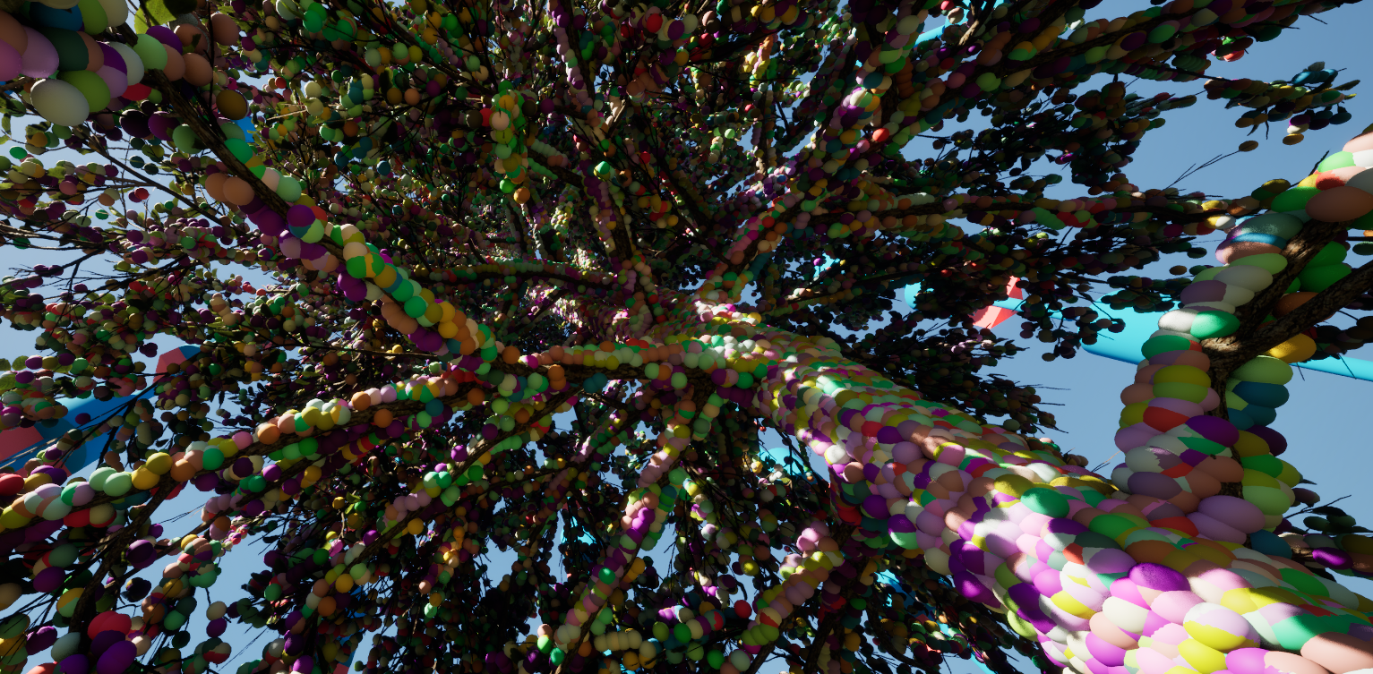
Sphere Size
When a scanner successfully registers a hit, a sphere is spawned at the hit location for visualization.
If you don’t need to see the points in real-time, disable sphere rendering in the Advanced Settings instead of setting this to zero.
Disabling spheres completely saves memory rather than generating invisible spheres.
Points Per Frame
This setting determines how many LineTrace operations each scanner attempts per frame (game tick).
Performance Considerations:
Higher values increase scanning speed but may cause frame drops on lower-end hardware.
To prevent indexing issues in parallel processing, this value is automatically adjusted to match factors of the horizontal/vertical resolution.
Example: If using a columnwise scan with a vertical resolution of 150, the system will adjust Points Per Frame to the closest valid factor of 150 (e.g., 1, 2, 3, 5, 6, 10, 15, 25, 30, 50, 75, 150).
Understanding Advanced Settings
Once you know your way around the regular settings and want extra customizability the advanced settings aim to provide you with a little bit more, all without requiring you to do any coding!
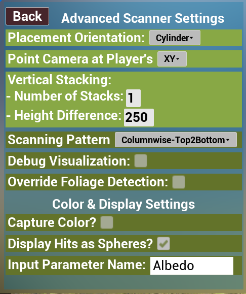
Placement Orientation
By default, scanners are placed in a ring around the player. This setting lets you change their placement pattern:
Cylinder (Default): Scanners are arranged in a circular formation around the player. Distance is controlled by Placement Radius.
Wall: Scanners are placed in a straight line, all facing the direction the player is looking. Distance between scanners is set by Placement Radius.
Ceiling (ALS-like Mode): Scanners are positioned above the player at a height equal to Placement Radius. They look directly downward, simulating an ALS (Airborne LiDAR Scanner).
Number of Stacks
Allows you to create stacked scanners (useful for Ceiling/ALS placement).
Total number of scanners = (Number of Scanners) × (Number of Stacks)
Height Difference
This value determines the distance the stacked scanners are from eachother. This setting has a unique interaction with the Ceiling placement orientations. For Ceiling/ALS placement orientation, this determines the lateral distances from scanners in both the X and Y axes.
Scanning Pattern
Probably an under-looked consideration; many times we just care about the points in a scan, not necessarily the order in which they were scanned. However some fast nearest neighbor algorithms take advantage of the locality of successively scanned points. This may be of use to some scientists and it was relatively simple to incorporate in the project so it is here if you need it. Due to race conditions & multiprocessing, in order to guarantee that points arrive in the order they are scanned, set Points Per Frame to 1 (if you care about this).
Debug Trace
If enabled, will show a debug linetrace including hit markers for geometry the linetrace registers as a hit. Use if you need to debug whether the scanners are hitting something they shouldn't or passing through an object they should be hitting. These linetraces use ECC_VISIBILITY so make sure that your objects have the visibility channel set to either Overlap or Block. This setting can also serve as a good educational tool if you are new to TLS/ALS and want to see how these things work visually.
Override Foliage Detection
As stated earlier in the documentation page; this plugin is aimed at working primarily with the Quixel Megascans vegetation library. As such it will ignore things that dont align perfectly with the naming schemes of these vegetative mesh objects. If you want this plugin to disregard these filtered checks and scan other mesh objects without assumptions, enable this setting. If a laser still interacts with a Quixel vegetation mesh with this setting enabled, it will work like normal; Enabling this override only adds more functionality, it doesn't remove any.
Capture Color
If enabled this will have the scanners attempt to capture RGB information about it's hits. In order for this to work correctly, your object needs to satisfy some criteria.
Your scanned object needs to have an Input Parameter named 'Mask' that contains Opacity, Translucency, and Roughness encoded in the R,B,G channels respectively. This allows it to pass the foliage detection filter.
Your scanned object needs to have an Input Parameter for its RGB Texture UV. This can be named whatever you want, make sure it matches the string in the InputParameterColorName advanced scanner setting.
If this is enabled and you see FColor::Black spheres being placed instead of the visual color of the surface you are scanning, that means that either your mesh didnt pass the foliage detection filter (see above); or the InputParameterColorName advanced setting is not set correctly.
If disabled, a laser will generate a random color to set its spheres. Black spheres are reserved for hits that dont pass the foliage check (only if override foliage detection is enabled).
Input Parameter Color Name
If <Capture Color> is enabled, the scanner will look at the scanned mesh's Input Parameters for one that matches this field for the UV Texture containing RGB values. By defaults, Quixel Megascans store RGB texture UV's in an input parameter named 'Albedo'. If the mesh you are working with stores them elsewhere, change this value to match the input parameter you need.
Display Hits As Spheres
If enabled, valid hits will generate a sphere at the hit coordinates. This helps to visualize your pointcloud before exporting it.
Exporting your Point Cloud
Exporting Your Point Cloud
When exporting your scanned data, the plugin provides options to control how the point cloud is formatted to match your application’s needs.
YZ Axis Swap (Coordinate System Adjustment)
Unreal Engine's coordinate system treats the Y and Z axes differently than many other 3D software tools. To ensure compatibility, there is an option to swap the YZ axes in the exported .xyz file.
Enabled by default to match most external software conventions.
Disable this option if you want to keep Unreal’s native coordinate orientation.
Single vs. Separate File Export
By default, all scanned points are exported into a single .xyz file. However, if your research or application requires separate scans per scanner, you can enable the Export Separately option.
Single .xyz file (default):
Combines all scanned points into one file.
Separate .xyz files (enable "Export Separately"):
Generates an individual file per scanner, which is useful for co-registration problems where you need to align multiple scans independently.
Color Data in Exports
If color capture was enabled during scanning, the exported file will include RGB color values for each point.
📌 Output format (per row):
X, Y, Z, R, G, B (where X, Y, Z values have 32-bit floating point precision, and R, G, B values are in the range 0-255)
If color capture was disabled, the output will only contain X, Y, Z coordinates.